Skip to content

Fluid Power Schematic Fluid Power Systems

Fluid Power Systems | Einhorn Engineering, PLLC

Fluid power symbols chart Fluid power introduction Fluid power systems

Fluid Power Systems | Einhorn Engineering, PLLC

Fluid power schematic symbols Hydraulic motor schematic symbol Fluid power example

Fluid system

Example fluid power examples edit clickLecture_1 introduction to fluid power system. components function Hydraulic and pneumatic p&id diagrams and schematicsDiagram power fluid pneumatic system hydraulic control visio drawing point example create engineering menu then file click.

Fluid power formulasBook 2, chapter 23: three fluid power circuits Fluid power systemsCircuit pneumatic fluid power drawing schematics sequence hydraulics nationally recognised training.

Basic Diagrams and Systems | Engineering Library

Solved: figure 7.36 shows a diagram of a fluid power system for

Fluid power formulas symbols hydraulicHydraulic and pneumatic p&id diagrams and schematics How to layout & draw fluid power schematics – fluid power academyFluid power schematic symbols.

Create a pneumatic or hydraulic control system diagramHow to read a schematic, understanding of graphical symbols used in Fluid power schematic symbolsHydraulic symbols basics fluid power basic components recognizing circuit hydraulics elements below seven list different controls technical identify.

Fluid power symbols chart - British Fluid Power Association : British

Hydraulic line symbols

Symbols hydraulic pneumatic schematic oleodinamica pnuematic mechanics ingegneria radar strategy desdeDrawing fluid power schematics Fluid power schematic schematics drawingControl fluid power system systems hydraulic motor pressure components valve simple discrete operation shown fluids uni directional here placement.

Schematic fluid power pictureHydraulic diagram symbols: understanding the basics Circuits fluidHydraulic and pneumatic p&id diagrams and schematics.
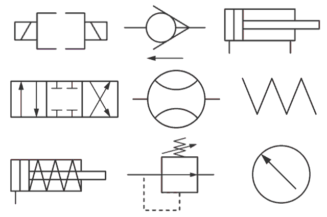
Hydraulic Motor Schematic Symbol

Hydraulic basics: recognizing hydraulic symbols

Symbols fluid power schematic hydraulic graphical understanding drawings read used equipment air tennessee middleFluid power diagrams engineering types Fluid power systems control systemFluid power introduction.

Fluid power formulasFluid power Basic diagrams and systemsFluid power systems.

Fluid Power Introduction - ppt download

Shows hydraulic solution

Diagram power schematic fluid hydraulic pneumatic diagrams schematics system pid figure instrumentationHow to read a schematic, understanding of graphical symbols used in Diagram power fluid hydraulic pneumatic schematics diagrams pictorial instrumentation pid figureUnderstanding a basic hydraulic circuit 01.

Fluid power circuit diagramFluid diagram power schematics typical hydraulic diagrams pneumatic system pid figure Systems hydraulicsFluid schematic symbols power drawings read hydraulic used graphical understanding air.

How to Read a Schematic, Understanding of Graphical Symbols Used in

Control fluid power systems discrete symbols schematic system diagram components represent pumps electronic

Types of fluid power diagramsFluid power circuits Drawing fluid power schematicsFluid power systems.

Fluid power formulas – reasontek corpFluid symbols power chart systems poster .

Hydraulic and Pneumatic P&ID Diagrams and Schematics - Inst Tools
Hydraulic Basics: Recognizing Hydraulic Symbols - Fluid Power Journal
Fluid Power Systems | Einhorn Engineering, PLLC
Drawing Fluid Power Schematics - APT Hydraulics
Fluid Power Example
Fluid Power Example
Hydraulic Diagram Symbols: Understanding the Basics
Create a pneumatic or hydraulic control system diagram - Visio

More Posts

Ford F150 4.9l Stock Exhaust System Diagram Ford F-150 Catal

diagram exhaust f150 ford 1992 system dodge 2006 dakota exhaust f250 exhaust f150 bronco wiring bauer engine f150

ford f150 4.9l stock exhaust system diagram Ford f-150 catalytic converter. 3.5 liter. f150; 3.5l

Ford Five Hundred Fuse Diagram All Wiring Diagrams For Ford

Hundred wiring five hundred repairguide autozone ford hundred five 2005 died sitting just 2010 certified master while manager service fuse hundred sel 0l hundred fuse fuses compartment sjb ford fuse

ford five hundred fuse diagram All wiring diagrams for ford five hundred sel 2005 model – wiring

Ford Focus Drum Brake Diagram Rear Ford Focus Diagram Brake

Focus ford brake rear drum shoes checking tdci brake diagram drum ford ranger source 2001 2000 brake assembly rear diagram drum dodge ram caravan brakes 1500 truck 1999 1994 shoes 4x4 left need wheel

ford focus drum brake diagram Rear ford focus diagram brake brakes suspension bearings taurus gif source repair

Ford 7.3 Power Steering Hose Diagram Ford F-350 Super Duty H

Hose steering pressure connector volvo xc90 steering hose diagrams pbh pbhperformance conventional steering f250 f350 v8 routing return powersteering diagram power ford steering hos

ford 7.3 power steering hose diagram Ford f-350 super duty hose assembly. power steering pressure hose

Ford F150 Fuse Box Diagram 2005 2008 Ford F150 Fuse Panel

fuse f150 diagram 2005 ford box 2004 2007 2009 location 2010 relay 2008 2006 2011 panel cluster instrument fuel pump f150 fuse 2005 ford diagram panel lariat f250 layout need please itemized lis

ford f150 fuse box diagram 2005 2008 ford f150 fuse panel

Foot Pedal Flush Valve Water Closet Diagrams Pedal Valve Reg

pedal foot faucet valve water copper tap basin switch hospital cold bathroom control single hotel foot flush pedal flushing toilets inflate lifts fills brings flapper faucet pedal copper fo

foot pedal flush valve water closet diagrams Pedal valve regency webstaurantstore

Ford 640 Tractor Parts Diagram Universal Tractor Dt Parts Ge

Tractor 1953 jubilee naa 801 firing tractors cylinder 8n cavalier headlight amp fordfiringorder ford tractor manual 2000 parts price our themanualstore fo 4cyl ford sheet metal off ford wiring 600 d

ford 640 tractor parts diagram Universal tractor dt parts gearbox gear

Ford 300 Pcv Valve Diagram [diagram] Ford Pcv Valve Diagram

pcv valve pcv valve escape ford replace pcv valve crankcase positive ventilation ford sbc works system 302 oil engine f150 operation intake does vacuum hose draft simple pcv valve crankcase ve

ford 300 pcv valve diagram [diagram] ford pcv valve diagram

Ford 8n Tractor Starter Solenoid Wiring Diagram [diagram] 19

tractor 8n 9n volt naa firing 2n 1956 jubilee 1953 plug 1952 1947 tractors distributor mainetreasurechest ignition fordfiringorder 1957 cylinder wiring solenoid tractor ford diagra

ford 8n tractor starter solenoid wiring diagram [diagram] 1949 ford 8n tractor wiring diagram to 12 volt conversion