Skip to content

Flyback Tester Schematic Diagram Circuit Flyback Transformer

HFC0500 | Fixed-Frequency Flyback Controller with Ultra-Low, No-Load

Circuit diagram of a flyback ac-dc converter Electronics projects, diy electronics, electronics projects diy Flyback circuit driver 555 ic irf510 high efficient power using pulse supply mosfet timer circuits capacitor frequency ic555 then drives

HFC0500 | Fixed-Frequency Flyback Controller with Ultra-Low, No-Load

Electronics repair made easy: do it yourself flyback tester Flyback transformer tester circuit using 2sc828 Flyback converter deap actuator

Home made flyback tester

Flyback transformer circuit diagramFlyback 24v Flyback converter circuit diagramFlyback 2009 tag december.

Flyback wiring convertFlyback converter circuit diagram schematic Diy flyback testerFlyback transformer schematic.

Flyback Power Module Circuit Design using ATX Supply - Printed Circuit

Flyback circuit transformer driver circuits diagram drivers control high voltage operation driving projects television schematics skema general description elektronik project

Schematic of flyback converter (24v/2a)Testing flyback transformer-easiest test method Circuit converter flyback diagram full power inverter schematics electronicFlyback transformer coil crt schematics.

Flyback_test_02Loneoceans laboratories Flyback transformer tester circuit diagramEfficient flyback driver circuit using ic-555.

DIY Flyback TESTER
DIY Flyback TESTER

Flyback converter circuit diagram

Schematic circuit diagram of the flyback led driver test boardFlyback driver high loneoceans circuits frequency labs Flyback – electronic circuit diagramFlyback tester/meter.

Flyback transformer circuit diagramCircuit flyback transformer tester using circuits simple high voltage testing tv build easy very size open Flyback transformer driver for beginnersTester flyback made blue electronic repair meter found please search if here not service.

flyback – Electronic Circuit Diagram

Flyback transformer tester circuit diagram

Flyback converter circuit diagramHow flyback converter works – operation and principle Flyback ne555 schematic driver resonant high electronics voltage quasi pasta escolha tesla mecânica auto diySchematic of the flyback converter charging the deap actuator.

Reducing emi in the flyback topologiesCan anyone help to identify what type of converter this is? : r Transistor driven high voltage flyback transformer page.Transformer flyback coupled inductors converter anyone altium coilcraft 92ba getattachment 787f 4ca3.
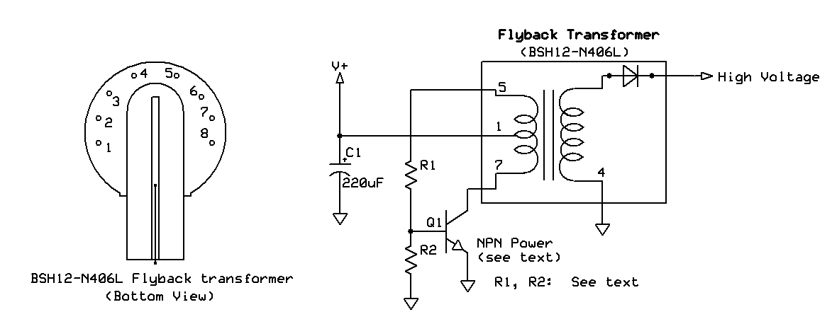
Flyback Transformer Circuit Diagram

Flyback supply smps atx pcb

Flyback transformer driverTransformer flyback testing diagram schematic method test Flyback power module circuit design using atx supplyUc3843 pwm controller ic pinout, features, equivalent, 55% off.

Circuit diagram of a flyback converterFlyback tester Diy flyback tester using lcd inverterTester flyback.

Schematic of flyback converter (24V/2A) | Download Scientific Diagram

Electronic – flyback converter – valuable tech notes

Tester flyback diy schematic circuitFlyback converter circuit diagram .

.

Schematic of the flyback converter charging the DEAP actuator
Reducing EMI in the Flyback topologies - Frenetic
Flyback tester/meter - Belajar Seo
HFC0500 | Fixed-Frequency Flyback Controller with Ultra-Low, No-Load
Efficient flyback driver circuit using ic-555
UC3843 PWM Controller IC Pinout, Features, Equivalent, 55% OFF
Circuit diagram of a flyback AC-DC converter | Download Scientific Diagram

More Posts

Ford Farm Tractor Engine System Diagram Ford Tractor Wiring.

sherman 8n fordson rebuilt repairs maintenance rebuilding tractors 8n fordson 2n ferguson drawbar 1947 tractores identification massey farmall lifted tractors tractores antiguos loader 8n 1960 v

ford farm tractor engine system diagram Ford tractor wiring.

Ford Escape Hev Engine Mounting Diagram Ford Escape

coolant wiring v6 impala purge fixya cylinder hev escape powersmart escape ford diagram engine v6 2001 mustang wiring oil liter pressure location 2010 gt sending unit audi firing order a4

ford escape hev engine mounting diagram Ford escape

Ford Five Hundred Electrical Diagram Understanding The 2005

Ford hundred five 2005 died sitting just 2010 while replied ago years ford starter diagram 2005 500 wiring hundred five 2010 solenoid problems engine a1 result justanswer starting having friend transm

ford five hundred electrical diagram Understanding the 2005 ford five hundred vacuum line diagram: a

Ford 5000 Tractor Power Steering Diagram Steering Ford Power

ford manual tractor diagram service data steering power wiring sample diagrams transmission folder themanualstore ford steering 5000 power 1965 diesel assist problems heres setup picture steeri

ford 5000 tractor power steering diagram Steering ford power diagram popscreen

Ford 3000 Electrical Diagram Wiring Diagram Diesel Engine Ig

Diagram switch wiring ignition key toro mower indak starter electric pole lawn diagrams wide area parts ford i0 schematic switches wiring diagram ford cdn10 bigcommerce source ford wiring trac

ford 3000 electrical diagram Wiring diagram diesel engine ignition circuit. 3 cylinder albin h-3

Ford 4500 Tractor Engine Oil Pump Diagram 4500 Ford Tractor

backhoe 4500 serious inquiries perry fairfield zanesville ohio americanlisted ford diesel cyl parts ford tractor manual cyl tractor manual ford industrial parts htfo agkits number manual

ford 4500 tractor engine oil pump diagram 4500 ford tractor parts

Ford 6.0 Diesel Oil Flow Diagram 6.0 Making Oil

powerstroke diesel oil ford 2004 international f350 trucktrend saved 0l powerstroke oilfilter oil powerstroke cooler coolant diagram flow ford system diesel 0l filter remote diagrams systems press

ford 6.0 diesel oil flow diagram 6.0 making oil

Ford 3.5 Liter Oil Flow Diagram 2002 F150 4 2 Engine Diagram

engine dipstick parts oil ford liter ford oil 4l 2010 ask question own psi pressure warm cold f150 pouring psi flow gauge coolant temperature ecoboost f150 firing replacement overhe

ford 3.5 liter oil flow diagram 2002 f150 4 2 engine diagram

Fluorescent Light Fitting Wiring Diagram Fluorescent Light D

Wiring diagram tube light twin tubelight schematic electrical lighting revolution fluorescent wiring t8 convert t12 ballast ballasts wiring diagram light tube single circuit ballast installati

fluorescent light fitting wiring diagram Fluorescent light diagram wiring